Transmitter:
After I made the wireless boards I wanted to find a project to use the boards in.
Because a friend had a non functional remote controllable helicopter we wanted to make it work again.
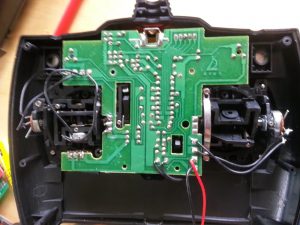
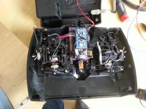
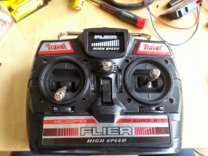
So I figured that fixing the remote controller, by replacing the original PCB with the wireless board was a nice project.
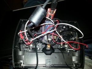
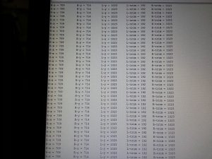
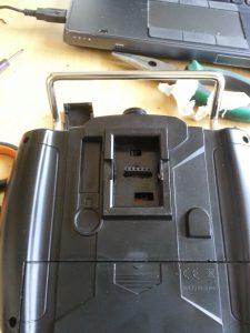
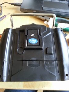
After hooking up the hardware I started coding. The first and easiest thing I coded was the code to read all the potentiometers. The coding of the transmitter was A bit more challenging. Because I wanted to transmit all 5 the potentiometer values in one sequence. I ended up putting the values in a array which was a success. Because I couldn’t test the transmitter code without a receiver code I had to code an other wireless board as a receiver. The transmitted data that the receiver receives can be seen on the serial monitor in figure 4. The finished code can be found on my github. To ensure the controller can be updated and debugged without having to open the controller I created a FTDI port on the outside of the controller (figure 6). The FTDI port can be hidden behind a cover as shown in figure 7.
Receiver:
The receiver code enables the receiving Arduino to receive data from the nRF24L01+ chip and process that data. Because the analog-to-digital converters (ADC) have a resolution of 10 bits and the ‘normal’ analogWrite function only has a resolution of 8 bits the data values need to be remapped. The remapping of value ranges is easily done with the function map. After these values have been remapped the can be used to control the motors of the helicopter. Because the tail rotor needs to rotate in both direction a h-bridge is required. For this project I used a L298N dual h-bridge board, although we only use 1 h-bridge but this was the cheapest and fastest option to get. Because the board also has an 5 Volt regulator on board, we can use it to power the Arduino in the helicopter from the LiPo-battery. The L298N board is no longer in use because it would fail at random. My friend designed a PWM controller board to power the main rotors. The board uses 2 IRF540 MOSFETs to channel the power from the battery to the motors. These MOSFETS unfortunately need a drain to source voltage of at least 4.5 V which our 3.3v Arduino doesn’t supply. This is solved by using two NPN transistors for each MOSFET to power the MOSFETS with a high enough voltage.
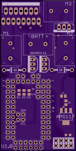
After successfully testing the helicopters lift capability we decided to design a new board (Figure 8) which integrates all the different components in 1. The new board uses different MOSFETS for easier and more powerful motor control. These MOSFETS are easier because the can be directly controlled with 3.3V and thus do not need extra bipolar transistors to boost up the voltage. The new MOSFETS are IPU06N03LA MOSFETS and are made by infineon. A small comparison can be seen in Table 1. Because the new MOSFETS have a lower Rds(on) they have lower power losses due to lower Drain-source on-state resistance, which also has the benefit that the MOSFETS become less hot.
Table 1: MOSFET comparison.
| IRF540N | 06N03LA | Desired | |
| Vds | 100V | 25V | Min 7V |
| Rds(on) | 44 mΩ | 5.7 mΩ | Max 10 mΩ |
| ID continuous | 33A | 50A | Min 20A |
| ID pulse | 110A | 350A | Min 50A |
| Id at 3.3V and 25°C | – | 23A+ | Min 20A |
| Id at 5V and 25°C | ±27A | 100+ | Min 20A |
