The project
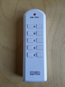
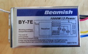
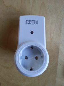
I’m currently working on automating my remote outlets. To start I’m going to build a central remote control unit. The first step is controlling my Impuls outlets (Figure 3) and if that’s successful I’m going to try and add some automated features like shutting all my power outlets off when leaving the room. Controllin my Beamish BY-7E light switch (Figure 2) is also in the planning. I bought the Impuls outlets in the Action, a series of shops in the Netherlands. For 10 euros you get 1 remote and 3 outlets which is a seriously low price. The Beamish BY-7E was bought on dx.com for about 13,50 dollar.
Hardware
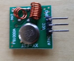
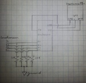
Before opening the remote outlets I was planning on adding an nRF24L01 module or a Bluetooth module to each outlet. But after opening the outlets I found the relatively unknown and badly documented … chip in them. But in the transmitter I found the commonly used and good documented HX2262 chip. The HX2262 chip is also compatible with the SC5262 and PT2262 chips and can be replaced by an Arduino running the right software. These chips make my projects a lot easier, cheaper and safer, because the receiving units are already finished when buying them. The only thing I need to build is my own transmitter. This is done by connecting a 443.29 MHz super-regeneration transmitter that uses On-Off Keying (OOK) to an Arduino. The module I used (Figure 4) costs about 2 dollar on dx.com and can be bought on many different sites.
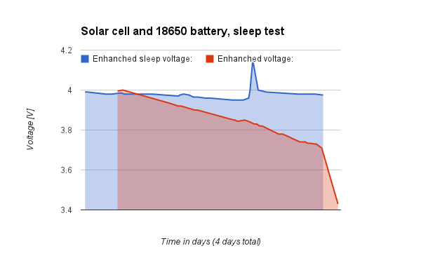
Because I find using normal buttons a bit boring and because you can’t change the button layout easily I decided to add a touchscreen to my control unit. The touchscreen I’m using is a Nintendo ds lite touchscreen, because these are easy to read out and are about 3 dollar per unit. I use the BOB-0917 break outboard from Sparkfun to connect the touchscreen to my Arduino. I’m not really happy with this board because it needs a piece of paper between the touchscreen cable ribbon and the connector to make a good connection. And this board also lacks pull-up resistors for a stable analog read out. But for now I don’t have an other option so I use a breadboard to connect the pull-up resistors. The current test rig can be seen in figures 5 and 6. The next challenge for me was powering the Arduino without using a power cord. I chose a 18650 battery and a solar panel combination because this combination can power the Arduino for a long time. Well that was the theory at least, so I began testing. After testing I concluded that this was a good combination if the Arduino could be in power down mode most of the time. In graph 1 you can see the result of my testing. You can also see that if the Arduino isn’t in power down mode most of the time that the power consumption of the Arduino is to high for these power sources. But extra power saving measures like desoldering the power led have not been done yet, but may be included in the future.
Software
For transmitting the right codes with the Arduino the best library to use is the Remote Switch library (not written by me). And for the touchscreen I have written my own library based on this tutorial. I think that using libraries makes the code better readable. Update: The library and Arduino code now work in perfect harmony together. Here is the beta version of my touchscreen library and here is the beta Arduino code that goes with it. You also need the RemoteSwitch library which can be found in the link above. I’ve created a github repository for this project here and will be using this to update my code and not the links from above.
Update 10-02-2014:
I created an other library to get the Arduino file smaller and more clearer. This library wasn’t working at first but Boris a friend of mine fixed the library for me. The new code and a movie demonstrating the setup will be uploaded this week, but currently I’m to busy to do that.
Update 14-02-2014:
New code was uploaded to Github and the video is uploaded here.
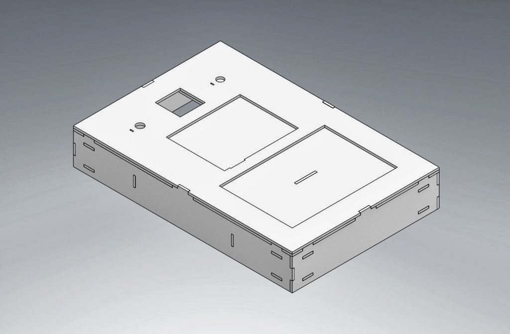
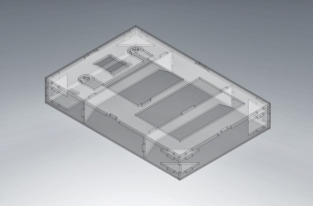
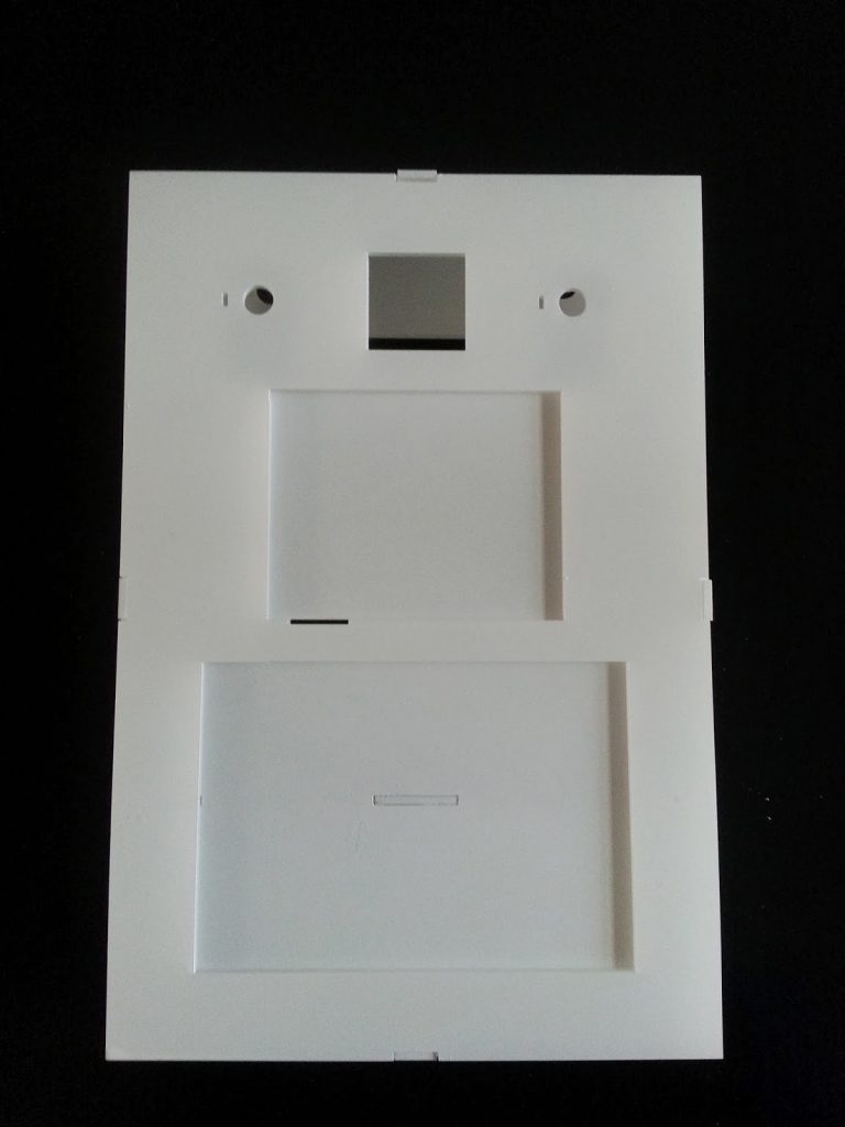
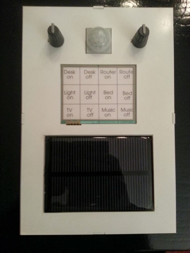
Hardware enclosure
All the hardware from the main control unit is going to be enclosed in a custom box that I’m going to make. The boxed is going to be made by gluing plates of PMMA that are cut with a laser cutter. Renderings of the box can be seen in Figure 7 and Figure 8. The cutouts in the box are for placing the solar panel, touchscreen, PIR-detector and two potiontiometers. The potentiometer and PIR-detector are for enhancements that are going to be added later on.